This article talks about the basics of flow profiles, installation criteria, end-user application considerations, and how to use flow conditioning to improve the accuracy of the insertion thermal mass flow meter in areas where a sufficient flow profile isn’t possible.
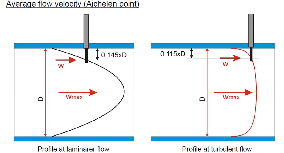
Number- 1: Understanding velocity profile
Inside a pipe, fluids, such as gas, flow at different speeds. When gas flows through a circular pipe, particles in contact with surface of pipe wall come to a halt (W0), forming a boundary layer. To maintain the mass flow rate through the pipe, the gas velocity in adjacent layers slows due to friction and the gas velocity in the midsection increases at centre is (Wmax). The velocity profile is the velocity distribution through the tubing. Fully developed velocity profile is almost parabolic, whereas turbulent profile is almost flat in nature. It is possible to determine velocity anywhere within the pattern by understanding the velocity profile.
Number- 2: ‘Installation location is critical’
The location of a flowmeter installation is crucial, but it is often ignored. It's common to make a location decision solely on the basis of ease of installation. Before putting a flowmeter in place, the end-user should think about the flow disturbances in the region. As a result, consider carefully which site would be the most successful. In any case, once the position ( either vertical or horizontal or inclined ) has been determined, define the disturbances so that the manufacturer can decide if flow conditioning is necessary or not.
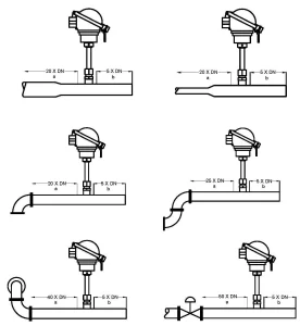
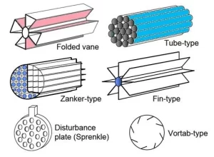
Number- 3: Flow conditioning requirements
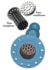
In industrial processes the flow profile is affected by several disturbances upstream of the flowmeter. If appropriate straight length is unavailable for measurement performance, there is a need to install Flow conditioning device as an option upstream for better performance with less upstream length. Flow conditioners (also known as flow straighteners) may provide a consistent flow profile near the sensor.
Number- 4: Process conditions
In industrial processes flow sensor will be exposed to various process conditions such as temperature & pressure variations, condensation of gases, gas mixtures etc. should be informed to Thermal Mass flow meter manufacturers for consideration for compensating all possible factor while parameterization and calibration to ensure optimal accuracy of the flowmeter.
Number- 5: Consideration in Flow sensor calibration
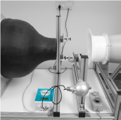
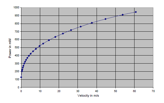
The flowmeter sensor probe should be placed in the wind tunnel velocity chamber with uniform velocity. When using a thermal mass flow meter to measure a gas, it's critical that the manufacturer understands the process conditions of the end user's application. This allows the manufacturer to calibrate the instrument to the conditions of the application's location. Flow rate in-accuracies will occur if this is not done. With a fully automatic calibration wind tunnel flow velocity versus sensor power is measured accurately programmed, to evaluate the relationship between mass flowrate and the signal for the gas and sensor under calibration, this step is repeated several times across the entire range.
Conclusion
When choosing a thermal mass flowmeter considering the above factors will ensure an optimal accuracy with desired performance.
LEOMI Instruments from Gandhinagar, INDIA has developed proven technologies and wide-ranging solutions for thermal mass flow meters with recognition of Startup India. A make-in-India with manufacturing facility meeting German technology standards, that allows them to optimize the life of industrial processes, equipment, and machines.
LEOMI’s products and expertise have helped flow measurement advancement in dozens of industrial applications including compressed air, combustion air, biogas, natural gas, flue gas, aeration air, corrosive process gases, and many more.
Author: Manish Patel – Director Leomi India


